Are there drawings available for the oiler on the big end of this engine? Thanks. George
——————
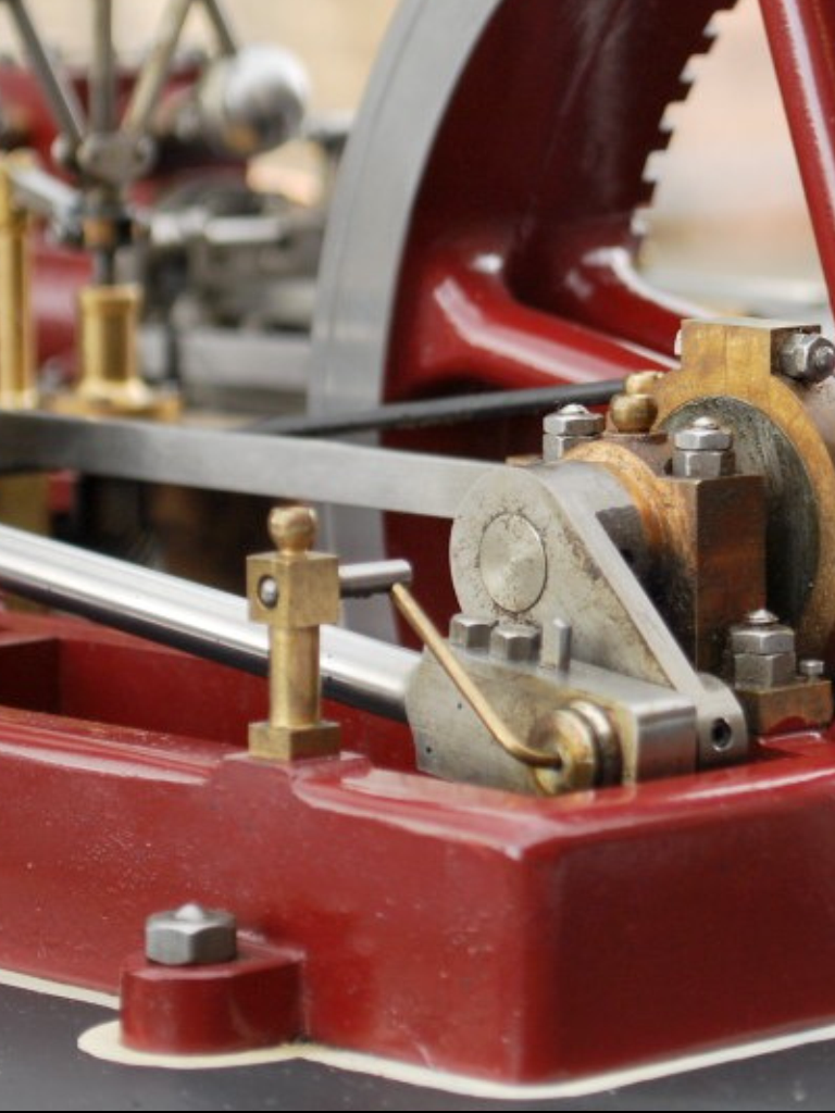
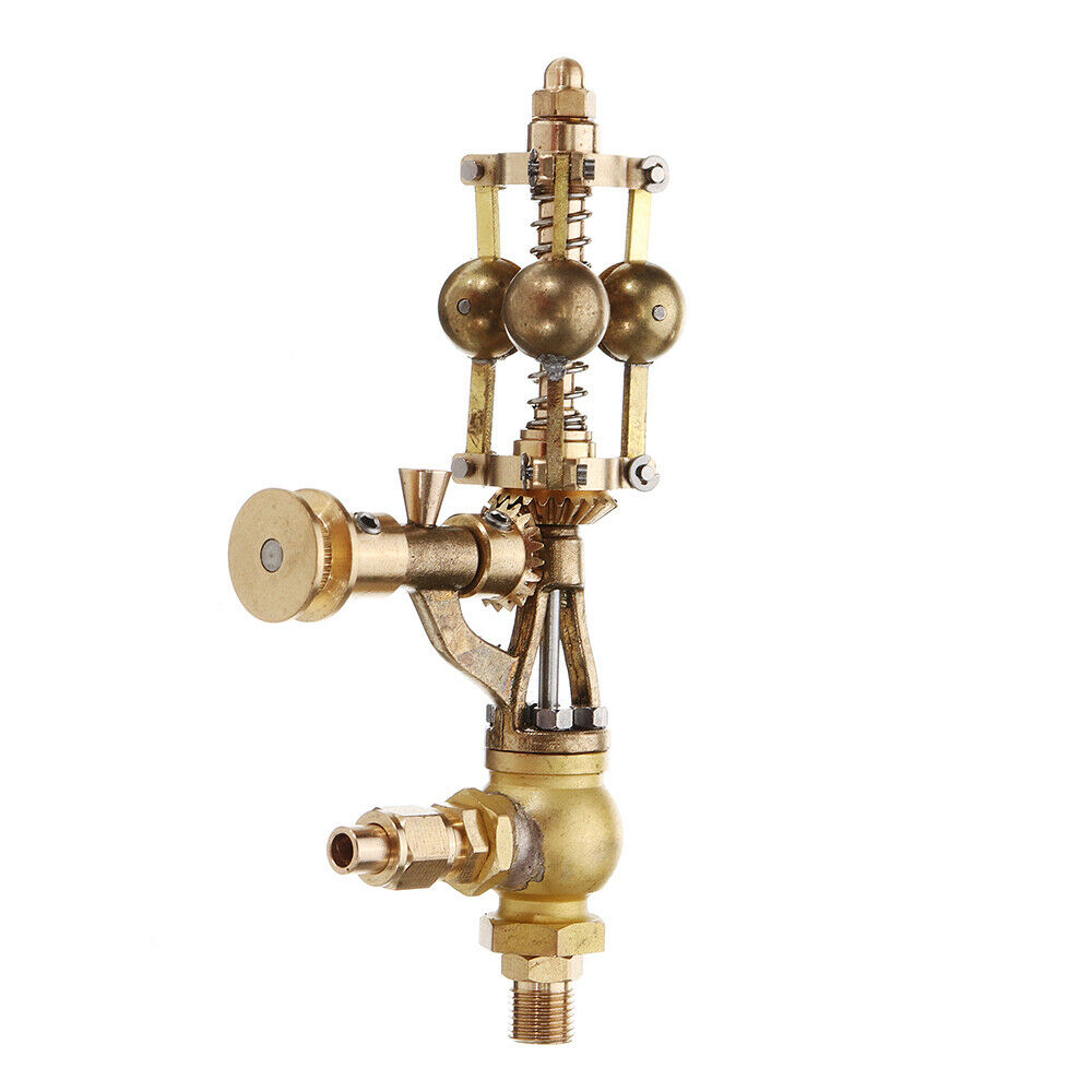
Hi George, A closer image. You can see that this is a representation of the original style oiler but is incorrect in several details.
———————-
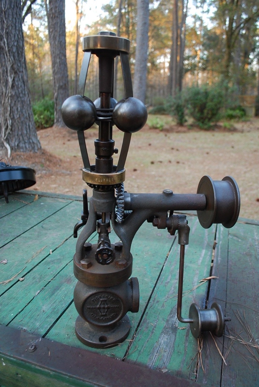
Hi there George, These oilers were quite popular on real engines as the oil pot was stationary and the feed can be regulated. The oil drips into the round bedpan like receiver, this has a tube that runs down to the big end, the oil being forced under pressure by centripetal force(centrifugal). At the scale of the Stuart Victoria’s they would be pretty tricky to manufacture and are probably for show as the connecting pipe thinness would be very restrictive for oil flow. As well as it being hard to manufacture the internal oil pathways. I certainly havnt seen any plans but I find that if you are trying to replicate a real life feature it is often better to source images of the real thing and work out the dimensions yourself. A closer look and I notice that it is missing key parts and thus is for display only. Check out the photo below.
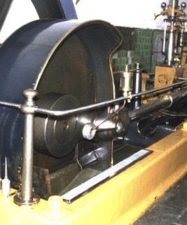
The oil jar sits on the rail, this feeds down a pipe suspended so that the end is in line with the crankshaft. A receiver that looks like a quality street tin in its side, with a large lip fitted is suspended also in line with the crankshaft and is connected to the big end by a pipe. Oil runs down from the reservoir and drips into the sweet tin running around the perimeter as the engine turns over. The pipe allows oil to be forced down to the big end. Oil pathways then allow oil to migrate along the bearing from the centre reservoir. I have a very old book that covers every aspect of steam engine design including every formulae required to calculate for example the diameter of the connecting rod based on the horsepower of the engine. I will have a browse and see if I can find a diagram of this oiler. Check out https://youtu.be/5G-M7-M5S8s. About 1:30 in to get a feel for what’s going on. Sorry for the rambling but am of sick at the moment and the painkillers kicked in when I read your email and am feeling a bit fuzzy headed now. Unless you are a total genius I would doubt getting a working version running and the picture you sent which is only an interpretation but not really don’t appeal to me, but it’s your engine. Please let me know how yours go.
Check out this video some nice closeups of the oiler.
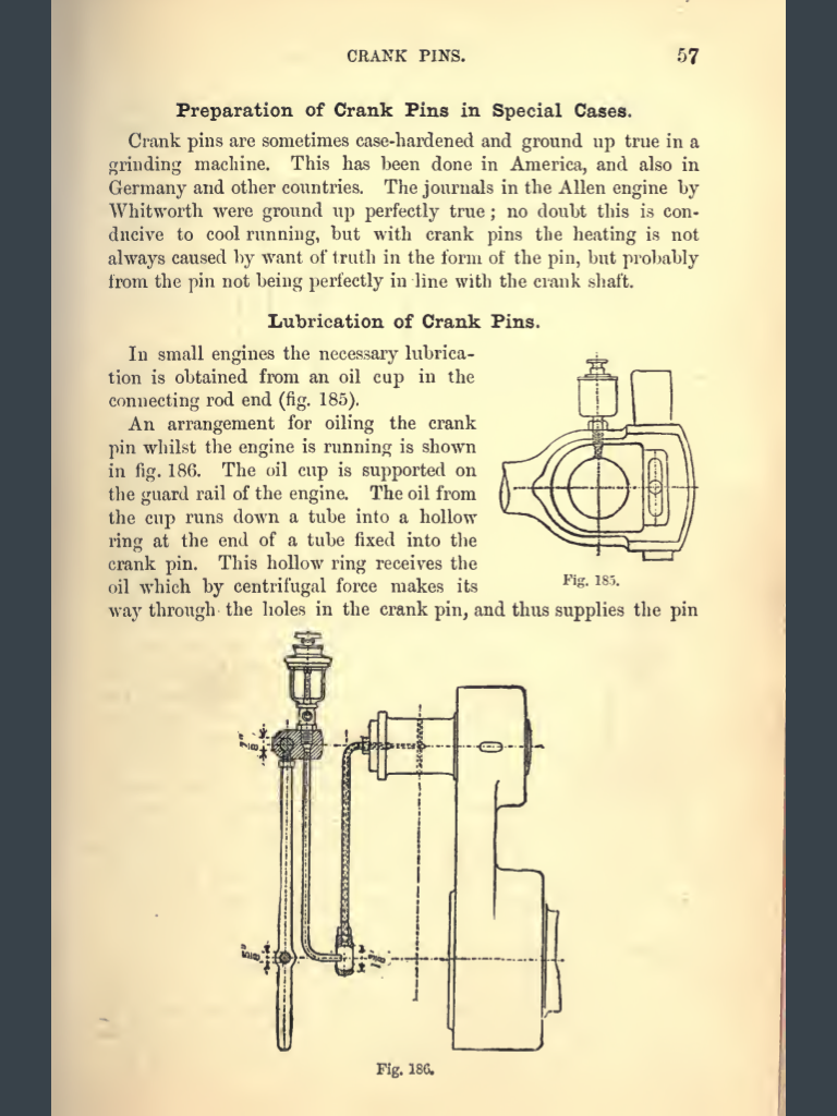
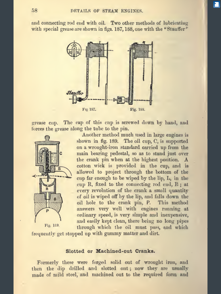
George, Check out these original drawings and text from a very old book on steam engines.
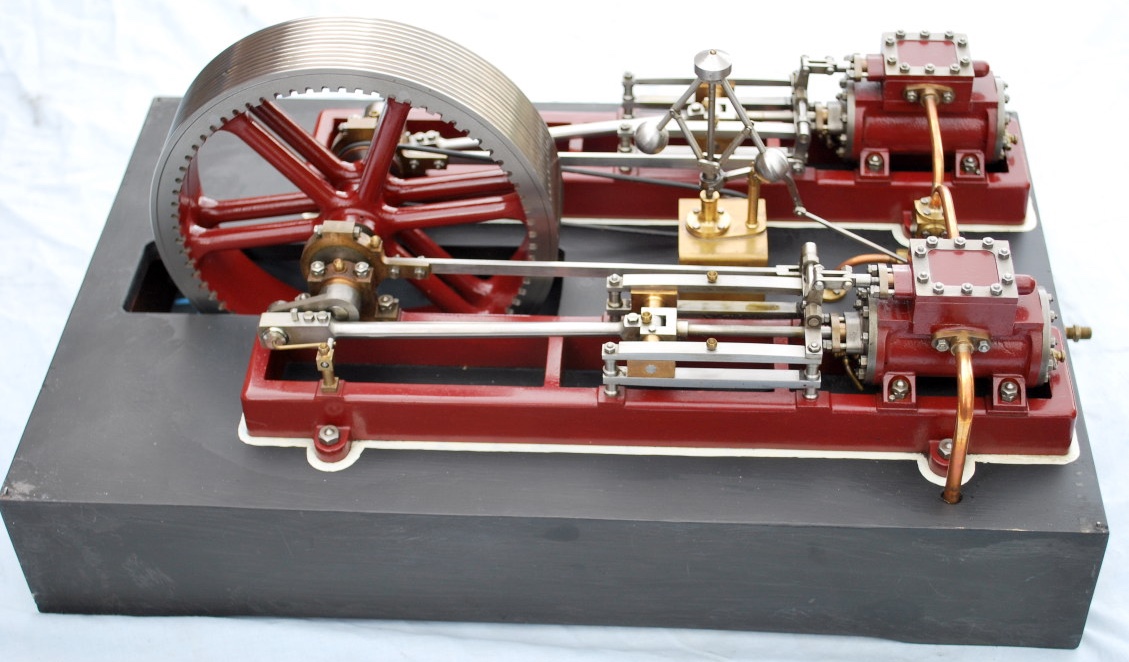
Are you working on a single or twin Victoria?.
OTHER ACCESSORIES
If looking to accessorise a single go with a barring frame and barring recesses on the flywheel. Or go for the microcosm governor from eBay https://www.ebay.co.uk/itm/174310002289
Or for the ultimate do what the did in real life when they wanted to upgrade an old engine like a Victoria, sleeve the old cylinder to reduce bore and add new piston. Add a second Victoria to side of engine but run them as a compound steam engine. Old cylinder now runs like a new HP cylinder, new cylinder runs as IP or LP cylinder. You don’t need twice the steam as you would with a simple twin cylinder and you get almost as much power as with a simple twin. Add a barring setup and a hot steam jacket round the connecting pipe between cylinders. Won’t run quite as well on compressed air but great on steam. Another nice feature is the wooden covering of the flywheel spokes. Many large engines had them as they improved aerodynamics and improved steam consumption. Check the video I linked in the other email. Gotta go for now look forward to hearing your ideas Steve