The High Speed No.1

- © 2018 Steve Allen Contact Me 0
No.2
2 in. Bore, 1 1/2 in. Stroke.
Finished Engines
£7 5s. 0d.
Fitted with reversing gear
£8 10s. 0d.
List of Castings and Parts.
CAST IRON. - 1 Cylinder with steam and exhaust ports cast in, 1 Bottom, 1 Cover, 2 Piston Bodies,
1 Piston Ring Casting, 1 Valve Chest, 1 Cover, 1 Standard, 1 Bed Plate, 1 Box bed, 1 Eccentric Sheave, 1 Balanced Disc Wheel, 1 Coupling.
CAST STEEL. - 1 Piston Rod and Crosshead, 1 Crank Shaft, 1 Connecting Rod, 1 Column,
1 Eccentric Rod.
GUN-METAL. - 1 Piston Gland, 1 Valve Gland, 2 Eccentric Straps, 1 Slide Valve, 2 Main Bearing Brasses, 2 Main Bearing Caps, 2 Connecting Rod Brasses, 1 Valve Spindle Guide, 1 Valve Nut, 1 each Steam and Exhaust Flanges.
MILD STEEL. - etc. -2 Crosshead Guide Plates, Cylinder lagging, Valve Rod, Steel for Valve Rod Head,
Head and Cross Head Bolt.
DRAWINGS. - A large sheet showing all details full size.
Price, packed in strong box, 20/-
EXTRAS
Complete set of Steel Studs, Bolts and Nuts, etc. Over 100 pieces, all made for the Stuart Engines ;
price 8s. 6d.
Cylinder Drain Cocks, 3s. per pair ; Cylinder Lubricator with single cock, 2s.
Reversing Gear Castings for Launch work with full size Working Drawing and all Bolts and Nuts etc. price 6/6.
A Fly-wheel may be ordered in place of disc wheel if engine is not required for direct drive. No extra charge.
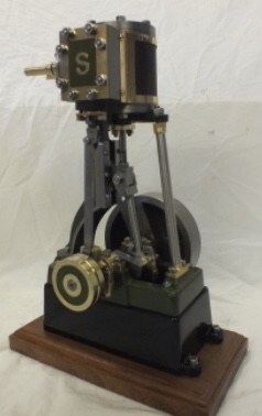
This engine is built from most of the same castings as the No.1 It has a deeper Piston with Cast Iron Ring, and having a shorter stroke, is suitable for very high speeds.
––––––––––––––––––––––––––––––––––––––––––––––––––––––––––––––––––––––––
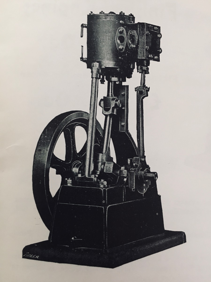
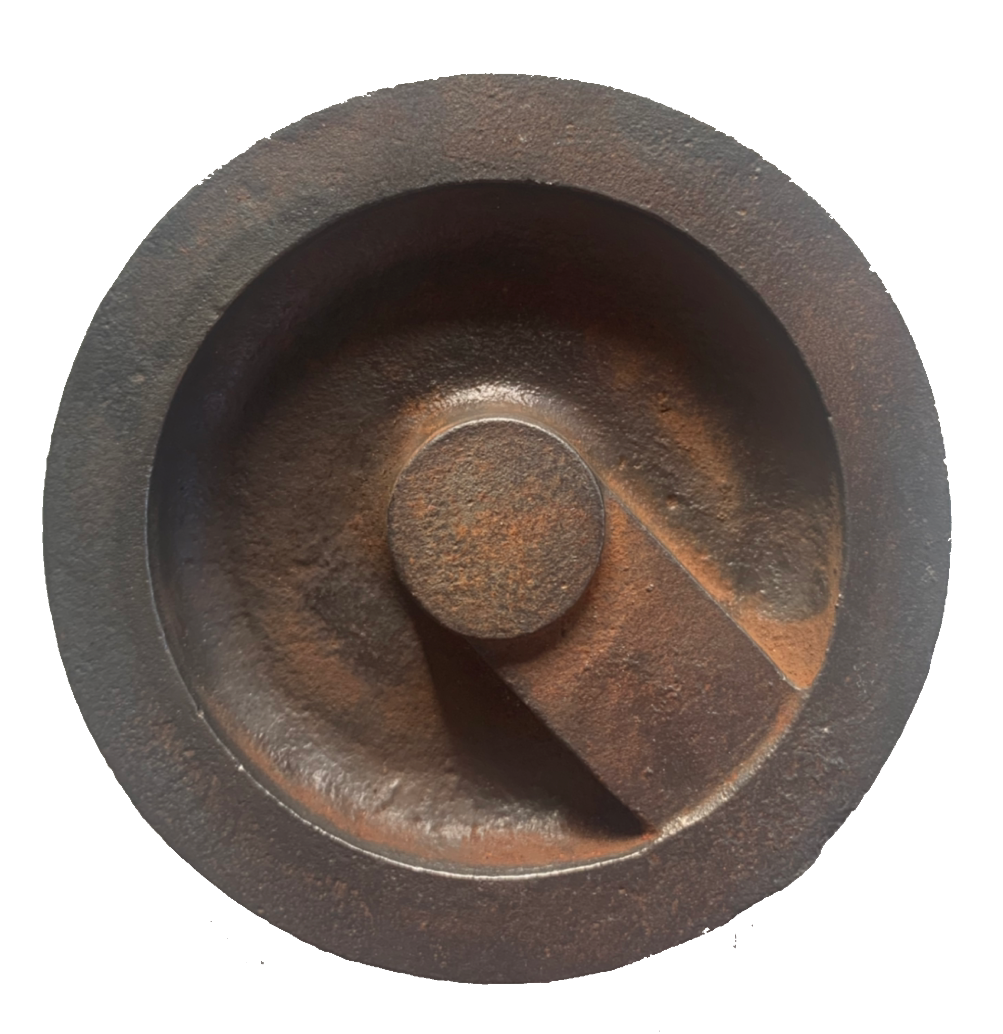
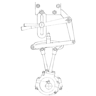
Having described the No.1 in such detail, describing the No.2 will be a bit brief as it is basically the same engine. Stuart states that the majority of the same castings are used. It is interesting that in the first Stuart catalogue that I have access to (1906) uses the same photograph for the No.2 as the No.1 which coincidentally is the same one used for Stuarts first advert in the 1901 Model Engineer magazine. The difference is the reduction in engine stroke, reduced from 2 inches to 1 ½ inches. This would have been achieved by reducing the Crank Web offset from 1 inch to ¾ inch. So a different crankshaft casting was used. The common use of the photograph for both engines implies that the Cylinder and Standard were the same. I think this is highly lightly as to create new castings would be an unnecessary cost. Reducing the engine stroke should not require changes be made to the standard. However using the same cylinder with reduced stroke results in a large unswept volume at each end of the stroke. This is not ideal and from the description in the catalogue this has been addressed by the use of a deeper Piston with Cast Iron Ring. The piston, made up of two castings, is now thicker by ½ inch and uses a single cast iron ring instead of the cast steel ring on the No.1. I am unsure about the change from a finished steel piston ring to a cast iron one. On modern No.1s there are 2 steel split piston rings, steel allowing for spring and a nice snug fit to the bore. The No.2 cast iron ring is apparently unmachined and as cast iron has little spring, would have to be machined to close tolerance of the bore, I wonder if it was of greater length as well. Until I can get my hands on a No.2 I will just have to wonder unless you have one and can let me know.* The No.2 appears to be the first to get a valve rod guide, as a later catalogue references the No.2 picture in the No.1 description, referring to the inclusion of the new guide. The No.2 also came as standard with the Disc Wheel, a Flywheel could be ordered instead at no extra cost. The Disc Wheel was probably introduced with the No.2 as the 1906 catalogue does not mention the Disc Wheel as an option for the No.1 but later catalogues do. The disc Wheel is interesting in that it has an asymmetric design. Cast into one side is a counterweight. This is to reduce vibrations at the higher speeds the No.2 runs at, caused by the lack of crank web counterweights. The counterweight appears as an approximately 1 inch wide rib running outwards from the raised hub to the rim. I have several photos of the Disc Wheel but only one shows the counterweight, due to it normally being placed adjacent the engine. It is clear that this is a cast web rather than a machined in web by the square corners where the web meets the rim.


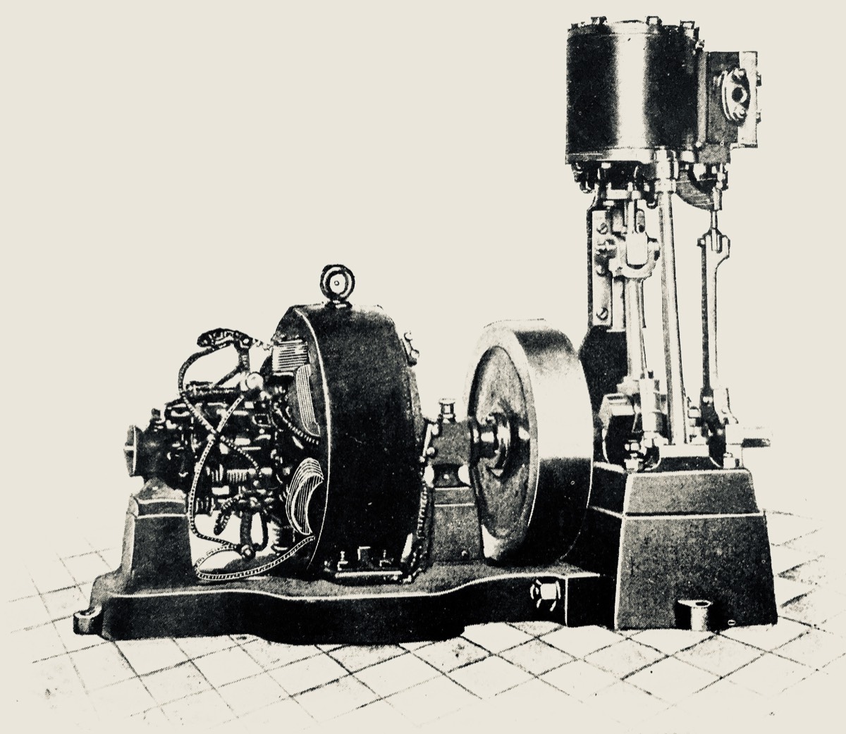
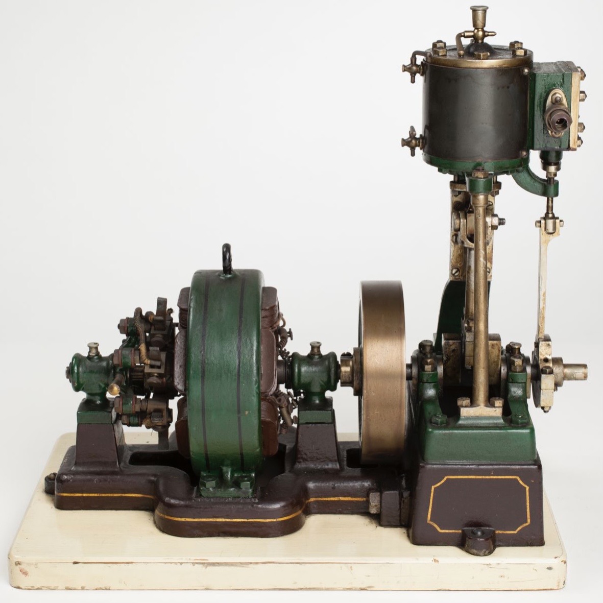
So why did Sydney release the No.2 engine, one with so few changes? To answer this question you need to consider what the No.1 was being used for. One of my favourite features of the Stuart catalogues over the years has been the inclusion of customer letters. As well as indicating the quality of parts and pride machinists had in their engines are descriptions of the uses they are put to. (I have included some of the more interesting descriptions in the sidebar ) Several people have described using Stuart engines to run dynamos to charge batteries for or to run lightbulbs directly. It may seem unreasonable to run lightbulbs from a steam engine driven dynamo but in the early 1900s not every house had mains electricity. My Grandfather had a sideline charging large lead acid accumulators for people in the remote village he lived in the 1920s. So for a small dynamo you do not need the BHP provided by a 2 inch stroke engine but the extra RPM’s provided by a 1 ½ inch stroke lead directly to greater voltage, and more light. The importance of the engines being used to run dynamos is clear as the 1906 catalogue lists 13 different models, several with multiple capacities. Pictures of different dynamos coupled to different engines, and the descriptions make it clear that although some were meant to be scale models of the real thing, others were designed for their practical use. Some of the dynamos are described as designed for use with a specific engine. Also included are tables for current and voltage performance with specific engines.

Please Consider Making a Donation