Stoking the steam, one engine at a time…

- © 2018 Steve Allen Contact Me 0
MAJOR BEAM
SET OF CASTINGS
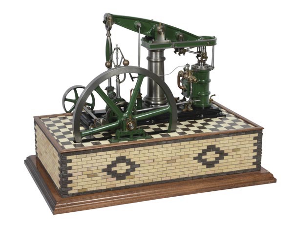
The Stuart Major Beam is typical of the smaller industrial engines of the 19th century, based on a eighth scale model designed by Mr. George Gentry and serialised in Model Engineer magazine throughout 1914.
Modifications were made to the engine 1968 by Mr. H A Taylor including reducing the cylinder bore, and redesigning the feed pump.
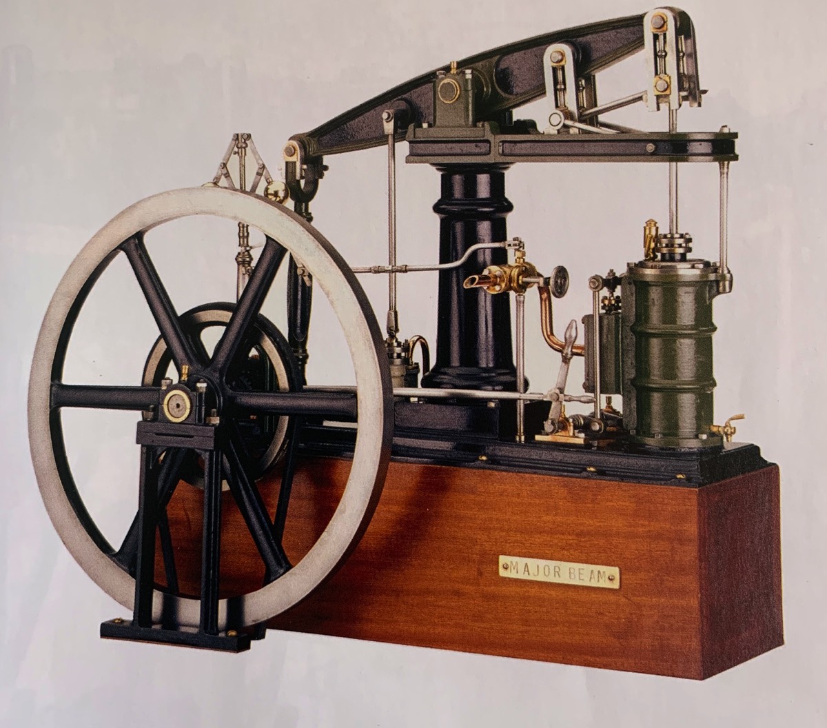
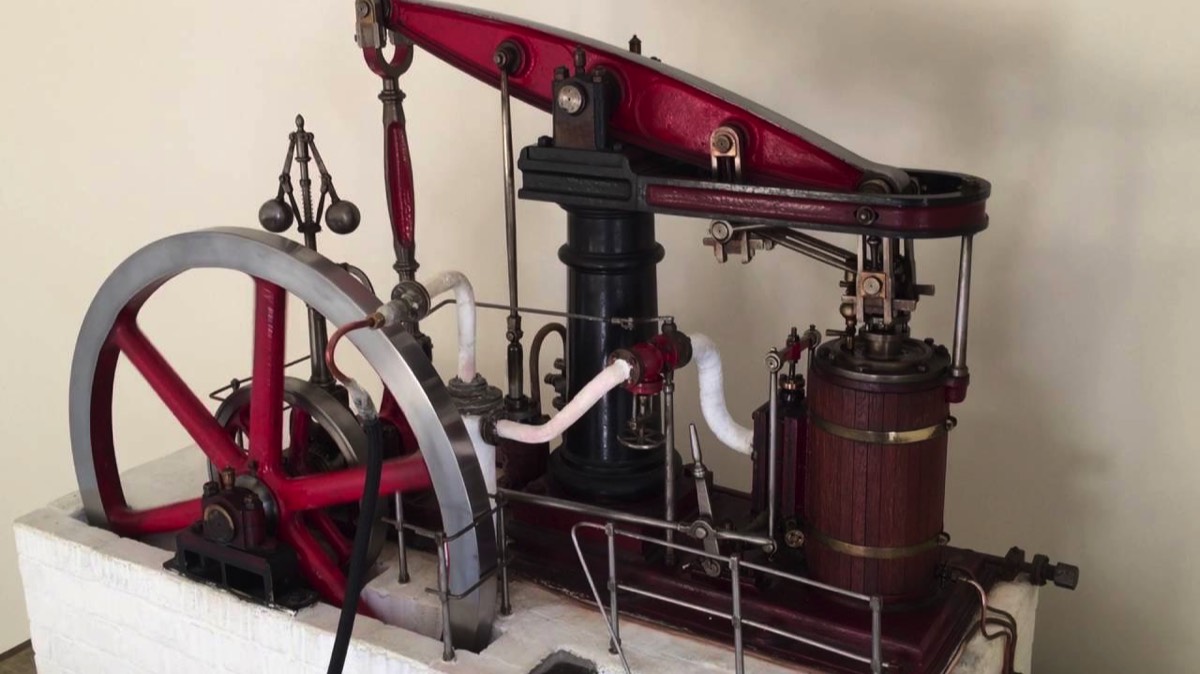
The engine is mounted on a bevel edged soleplate. This must be mounted on some kind of raised platform to allow for the flywheel and pulley both of which run below the soleplate. Typical bases are of wood or simulated brick or stonework. An alternate is to mount on a box with the flywheel sitting in a slot cut in the lid. On the soleplate is mounted the very tall cylinder. The valve chest is mounted on a raised part of the casting that houses the steam ways running to the end of the cylinders. The bottom appears to have no bulge for fitting a condensation valve, having seen the plans a few years ago I recall a plug fitted into the bottom of the cylinder that has an angled top angled down towards the steam way, this causes any condensate to be guided towards them and be completely vented at each stroke, a horizontal bottom to a cylinder allows condensate to pool and can cause hydraulicing. The ME beam does have a bulge at the bottom for a valve. Some Major beams have a valve fitted anyway. At the top of the cylinder the end cap has a raised donut ring near the edge just as on many real engines that allows oil leaking from the piston rod gland to collect without running down the side of the cylinder. The piston rod gland packing block is round with three studs and dunts securing it. A flat is machined on the side to allow clearance for the unusual valved cylinder oil cup. This is lidded so that it can be filled with oil, the cap screwed on and the valve opened to allow the oil to enter the cylinder whilst the engine is running. On the outside of the cylinder casting, opposite the valve chest, is a bulge for mounting a rod that supports the end of the U shaped support for the Watts motion. This parallelegram motion is designed to convert the curved motion at the end of the beam into a linear motion connecting to the top of the piston rod. Each of the many links is constructed from several decorative parts just like the real engine unlike many model beam engine designs that use simple bars or rods. The large beam, pivoted at the middele mounts the parallegram motion above the cylinder at one end and the Connecting rod at the other. An extra connection between the pivot and the Connecting rod is provided for connection to a boiler feed pump mounted on the soleplate.The connecting rod is cast with an intricate design similar to real engines, four flutes have been cast into the main rod lightening it whilst retaining strength. The Crank rotates and is allowed clearance by a curved trough moulded into the soleplate. When making a mount this must be taken into account as it will require a suitable cut out. The crankshaft runs in two bearings an inner one next to the crank and an outer one mounted on a seperate skeletonised standard. Also mounted ont eh crankshaft are a bevel gear that transfers drive to another bevel gear mounted on the bottom of the governor shaft. This is supported by a small arched bracket. The tall governor is a typical Watt type. A linkage connects to a valve mounted onto or adjacent the Valve chest cover providing speed control. Also mounted on the Crankshaft is a pulley, unusually mounted inboard of the flywheel and support standard. Many model engine mount any pulley on the end of a shaft so that it is easy to fit a drive belt. Fitting an unjointed drive belt to this engine would be problematic. On real engines drive belts were usually cut to length and joined so fitting was not a problem and the alternative, ropes would also be cut to length and spliced. Phe plans show the pulley with grooves cut for rope drive. Often multiple ropes would be used reducing the strain on each rope, also allowing the engine to continue running with the remaining ropes. The rope could then be replaced at a convenient moment. An eccentric and sheave are also mounted to the cranckshaft to run the valve. The round rod that connects to the valve lever is unusual in the it extends past the connection and has a handle machined into the end.before theis the rod connects to the valve lever by means of an inverted U hooking over a peg on the lever. The top of the lever also has a hndle machined on the top. This design is a direct callback to the real engines as early beams had the ability to disconnect the valve eccentric from the valve lever to allow manual independent valve manipulation. So if the engine is stopped in any position other than the two dead points, the operator can lift the eccentric connecting rod off the valve lever and move the valve lever back or forwards to apply steam to turn the engine over to the required position. When done the valve lever can be moved into position so the eccentric rod can be re-engaged. In wandering round the engine i have left out the major part, the column. This is hollow cast and is quite architectural with bulges and curves providing a pleasing outline. Now a quick note about the original ME engine. The main obvious difference is the repositiond pulley. The crankshaft now has a large gear instead of the pulley, driving a smaller gear that is mounted on a shaft, running in two small bearing blocks. This takes the drive to the back of the soleplate where a pulley is mounted hanging over the edge. Another difference is the cylinder casting. The manufacturer decided to simplify the casting so no steam ways are cast into the cylinder, instead a cast plate is mounted onto a flat machined on the side of the cylinder, this has half steam ways cast in. so when mounted is creates the required steam ways. A valve chest is then mounted on top of this casting. To indicate the difference in size between the two engines the Stuart has a 13 3/4 inch flywhell and the ME has a 9 1/4 inch flywheel.
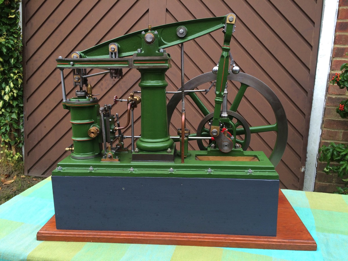
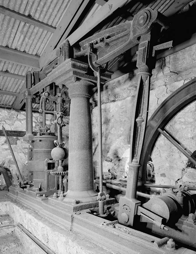
Originally appearing as a feature in the Model Engineering magazine the ME beam engine soon became a populare model when castings were made available by A.J.Reeves. The design was based on a real steam engine and was very true to its full sized equivalent. Stuart approached the designer and proposed making castings available but with a couple of modifications and deletions but more importantly of much bigger size. At first glance it is easy to confuse the two from photographs. In real life it is easier, if you can pick it up its an ME beam engine, if you would ask a couple of friends for help its the Stuart MAJOR Beam. So similar are they that at the time of writing an unscrupulous seller is trying to sell an ME Beam for the price of a Major Beam, it even has a brass plaque stating its a Stuart Major Beam. This is all despite me sending him proof. (A mojor beam sells for about 4 x the price of the much smaller and more managable ME Beam.)
Video of Major Beam running.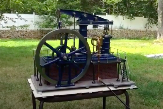

Please Consider Making a Donation